
Switches: the most engaging electromechanical component!
Available in all sorts of shapes, sizes, and configurations – switches give us the ability to interact with the electronic world. In this post, we’ll be covering a very particular type of switch technology that will help us design expression pedal controls and enable battery power switch-over.
Introducing: the switched jack.
As a member of the Reverb Partner Program and as an Amazon Associate, StompboxElectronics earns from, and is supported by, qualifying purchases.
Disclaimer: Stompbox Electronics and/or the author of this article is/are not responsible for any mishaps that occur as a result of applying this content.
Types of Audio Connectors for Guitar Pedals
There are two main types of audio connectors for guitar pedals, each with their own styles of plugs and jacks. They are:
- Mono connectors
- Stereo connectors
A mono connector has two electrical contacts: one for ground and one for a single audio signal.
A stereo connector, on the other hand, has three electrical contacts: one for ground and two for stereo left & right audio signals.
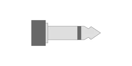
Mono Audio Plugs
Figure 7.1 shows a mono audio plug with the standard tip and sleeve (TS) connections. This is the most typical example of a mono audio plug. The tip connection carries the guitar signal while the sleeve serves as a reference, or ground, for the signal.
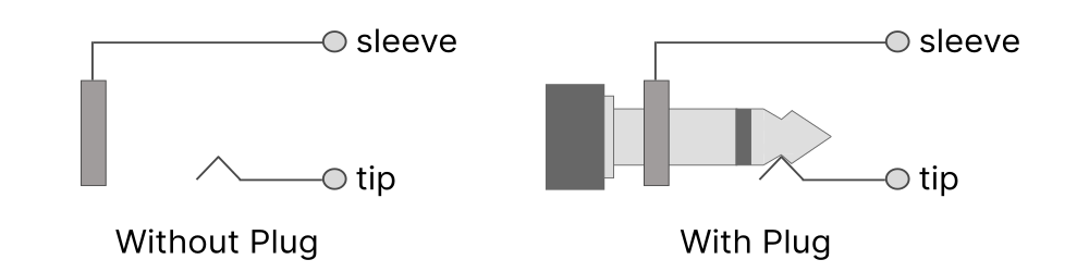
Mono Audio Jacks
Mono audio jacks are the complement to mono plugs, having just two connection points: one for the tip and one for the sleeve.
When the plug is pushed into the jack, the tip and sleeve make contact with their respective connection points.
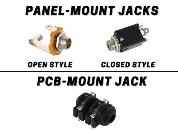
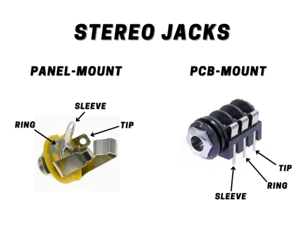
A panel-mounted jack is a type of jack you can install in a panel and is usually fastened with a nut and washer. Panel-mounted jacks usually come with lugs for soldering a wired connection.
A board-mounted (or PCB-mounted) jack has pins that are inserted into copper-plated holes on a circuit board. The jack is then soldered directly into the board.
Stereo Audio Jacks
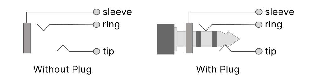
Stereo plugs come with a tip, ring, and sleeve connection. When distributing audio in stereo, the “left” and “right” signals travel on the tip and ring connections, respectively.
The sleeve serves as the ground reference for both signals, just like the mono configuration in the previous section.
Stereo Audio Jacks
Stereo audio jacks are used in conjunction with stereo plugs. Plugs are constructed with three connection points: tip, ring, and sleeve.
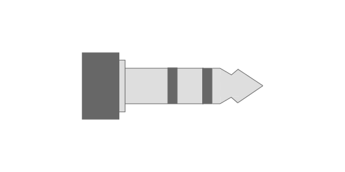
When a stereo plug is connected to a stereo jack the tip, ring, and sleeve make contact with their respective connection points (Figure 7.5).
Similarly to mono jacks, stereo jacks come in different mounting configurations: panel-mount and PCB/board-mount.
Switched Audio Jacks
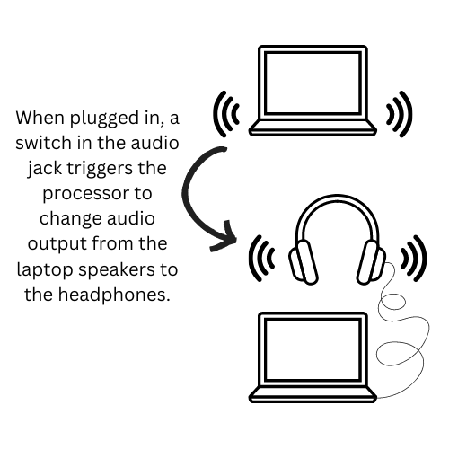
When you plug a pair of headphones into your laptop while playing music, what happens? The laptop transfers the audio signal from the speakers to the headphones automatically. This is all because of a tiny switch inside the headphone jack – a switched jack.
Other examples of switched jacks involve the use of expression pedals. Using the switches inside the jack, you can determine whether the Feedback control on a delay pedal should be controlled by a knob or by the expression pedal.
So how do these switches work exactly? Let’s take a look.
Switched Jack Schematic Diagram
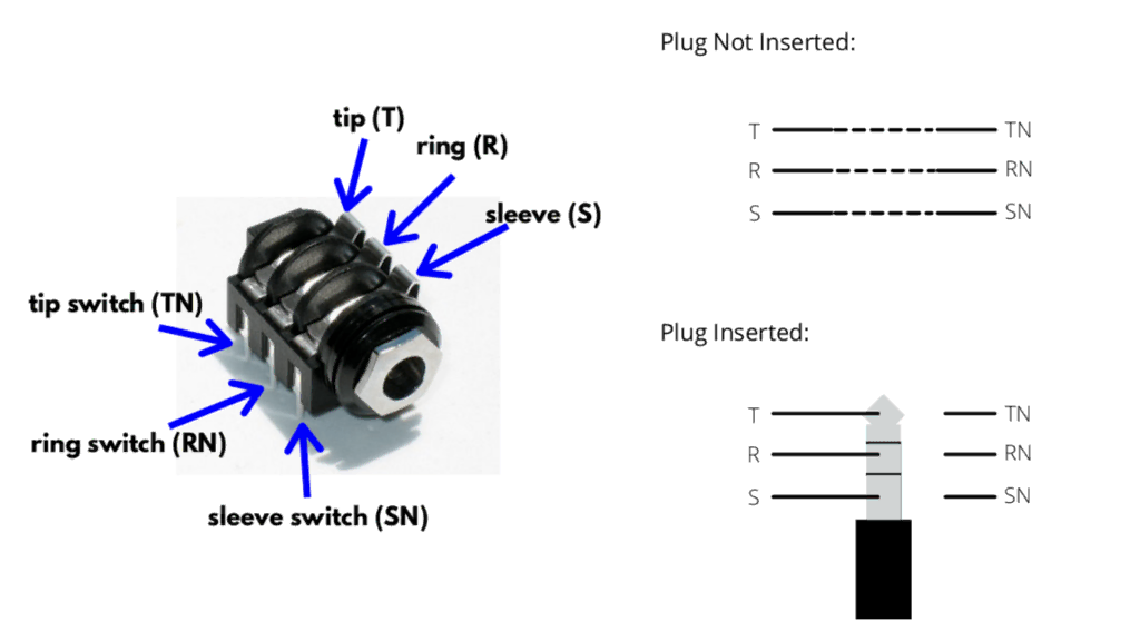
Switched jack operation is best explained using a diagram of the connectors. When looking at Figure 7.8, we see a stereo jack where the tip connection has an integrated switch, called the tip switch.
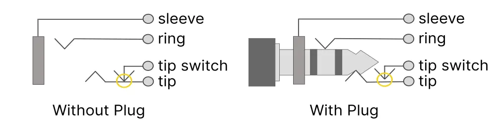
When the plug is not inserted into the jack, the tip switch is connected to the tip lug.
Inserting a plug pushes the tip connection out of the way so that the ‘tip switch’ disconnects from the tip, shown in the orange circle above.
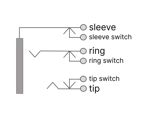
The same type of integrated switch can be installed for the ring and sleeve connections (Figure 7.9). Tip, ring and sleeve switches are commonly found on PCB-mount stereo connectors.
Switched Power Jacks
Let’s take a look at our favorite pedal series: the BOSS Compact Series. The DS-1 is powered using either a battery or a power adapter. When using the adapter, all the power is routed from the adapter, regardless of whether a battery is connected.
It’s all thanks to a switched power connector!
Power Jack Operation
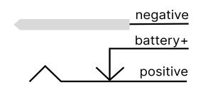
Power plugs have two contacts: positive and negative. For BOSS pedals, the center pin is negative and the outer sleeve is positive (center-negative configuration).
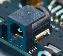
In practice, a switched power connector has 3 lugs. Two of the lugs take care of intercepting the positive and negative power rails. The third is a switched contact for the positive lug, which is used to power the pedal via battery when the adapter isn’t plugged in.
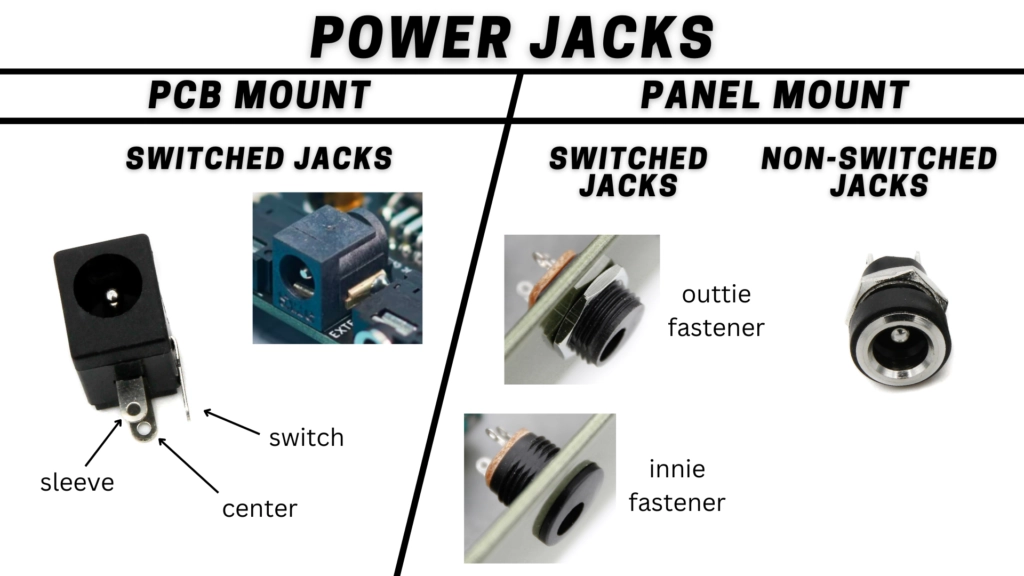
Types of Power Jacks
Similarly to audio jacks, there are a variety of configurations for power jacks. The largest difference is between panel-mount and PCB mount.
Among panel-mount style jacks there are switched power jacks, as well as non-switched. Additionally, among switched panel-mount style jacks, there are models that are fastened from the inside, and others that are fastened from the outside of the enclosure.
Guitar Effects Design in 48 Circuits or Less
The 48 Circuits or Less article series serves to close the gap between DIY guitar effects design and guitarists interested in the craft by uniquely curating the most important aspects of DIY guitar effect circuit design. This post is part of the 48 Circuits or Less series. View more articles in this series here.
Meet the Author:

Hi, I’m Dominic. By day, I’m an engineer. By night, I repair and modify guitar effects! Since 2017, I’ve been independently modifying and repairing guitar effects and audio equipment under Mimmotronics Effects in Western New York. After coming out with a series of guitar effects development boards, I decided the next step is to support that community through content on what I’ve learned through the years. Writing about electronics gives me great joy, particularly because I love seeing what others do with the knowledge they gain about guitar effects and audio circuits. Feel free to reach out using the contact form!
The Tools I Use
As a member of Amazon Associates, Stompbox Electronics earns and is supported by qualifying purchases.


