How to Test Electrolytic Capacitors on Circuit Boards
Important Note
I recommend that any circuit board repairs be supervised by a licensed professional engineer and be done under approved ISO and UL processes.
What is ESR?
Electrolytic capacitors tend to “dry up” over time. A conductive electrolyte (liquid) comprises the entire negative plate of the capacitor, forming the connection between that plate and the negative terminal. As the electrolyte evaporates over time, the capacitance decreases, and the resistance between the negative plate and the negative terminal increases. This resistance is known as ESR, or equivalent series resistance. An increase in ESR introduces an unwanted resistive component to the circuit. Low ESR is desirable, while high ESR is detrimental.
Often, but not always, a capacitor with high ESR is physically distorted or leaking. When capacitors are warm, the electrolyte is more conductive, and they tend to perform better than when cold. However, heat is their long-term adversary. A capacitor that runs hot won’t last as long as the same capacitor in a cooler environment. CLICK HERE for a more detailed article on Capacitor Failure Theory, Testing and What ESR is.
How to test ESR
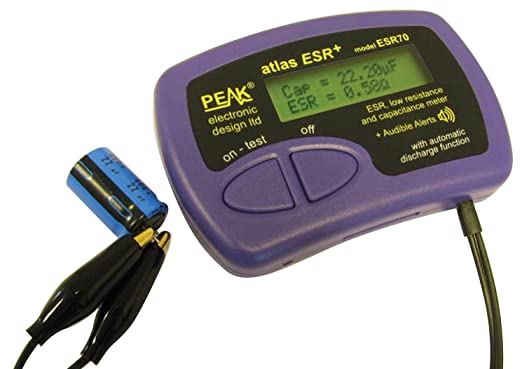
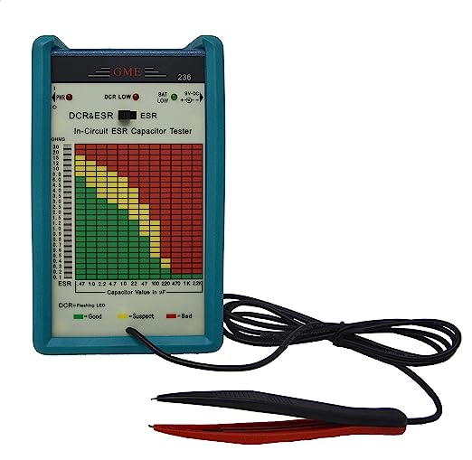
There are several popular meters available that can test for ESR. Some models display the result on a table, indicating whether it’s good or bad. Others provide an audible indication of pass or fail, accompanied by a supplementary table for further reference. While most of these meters can test capacitors in-circuit to some extent, they can still be influenced by the surrounding circuitry. For an accurate reading, it may be necessary to remove and test the suspect capacitor separately. Remember, it’s important to use the ESR meter to test all suspect capacitors, regardless of their physical appearance, as capacitors may not always exhibit visible signs of degradation. Below are examples of some common ESR meters.
ESR LOOKUP TABLE CHEAT SHEET – CLICK HERE
ATLAS ESR70 AUTORANGING ESR TESTER (CLICK HERE)
GME IN-CIRCUIT ESR TESTER (CLICK HERE)
Rules for Replacing Electrolytic Capacitors
Here are some fundamental rules for replacing electrolytic capacitors in circuit boards.
- Replace with exact type if available.
- Replace with capacitor that has the same capacitance (uF – microfarad) as the original.
- Replace with capacitor that has the same voltage rating or higher.
- Use higher temperature capacitors when possible (105c).
- Use capacitors with higher hour-ratings when possible ( > 5000 hours).
- Physical size matters – Larger capacitors have better heat dissipation capabilities, allowing them to run cooler and prolong their lifespan. However, when using larger capacitors, be cautious about the lead thickness. Modifying the holes to accommodate them can be risky, especially with multi-layer boards. The through-holes are typically plated to ensure connectivity between the top and bottom layers. If you need to drill out a hole to fit thicker capacitor leads, be mindful of this consideration.
- Combining caps can yield desired values as covered in the next section.
- When two capacitors are connected in parallel, their capacitances are added together. However, it’s important to note that the final voltage across the parallel combination will be equal to the lowest voltage rating among the two capacitors.
- When two capacitors are connected in series, the final capacitance is always lower than the value of the lowest capacitor (as calculated by a simple formula). The voltages across the capacitors, on the other hand, add together. However, it’s important to be aware that due to differing ESRs (equivalent series resistances) and the voltage division principle, the voltage may not split evenly between the two capacitors in series. If the capacitors have different capacitance values, the capacitor with the lowest capacitance will have a larger share of the voltage across it.
Rules for Combining Capacitors (Series and Parallel)
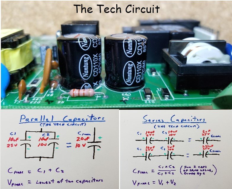
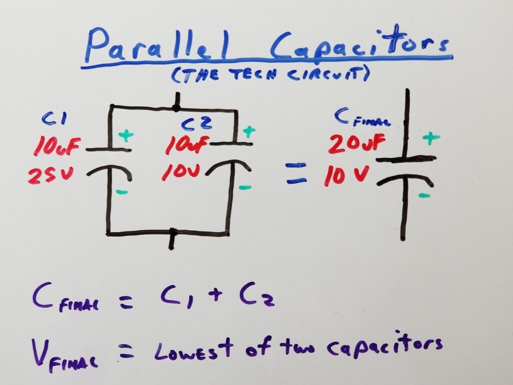
Parallel Capacitors
When two capacitors are connected in parallel, their capacitances are added together. However, it’s important to note that the final voltage rating will be determined by the capacitor with the lowest voltage rating. Ensure that the positive sides of the capacitors are connected together and the negative sides are connected together. Below is an example of creating a 20uF capacitor with a 10V rating:
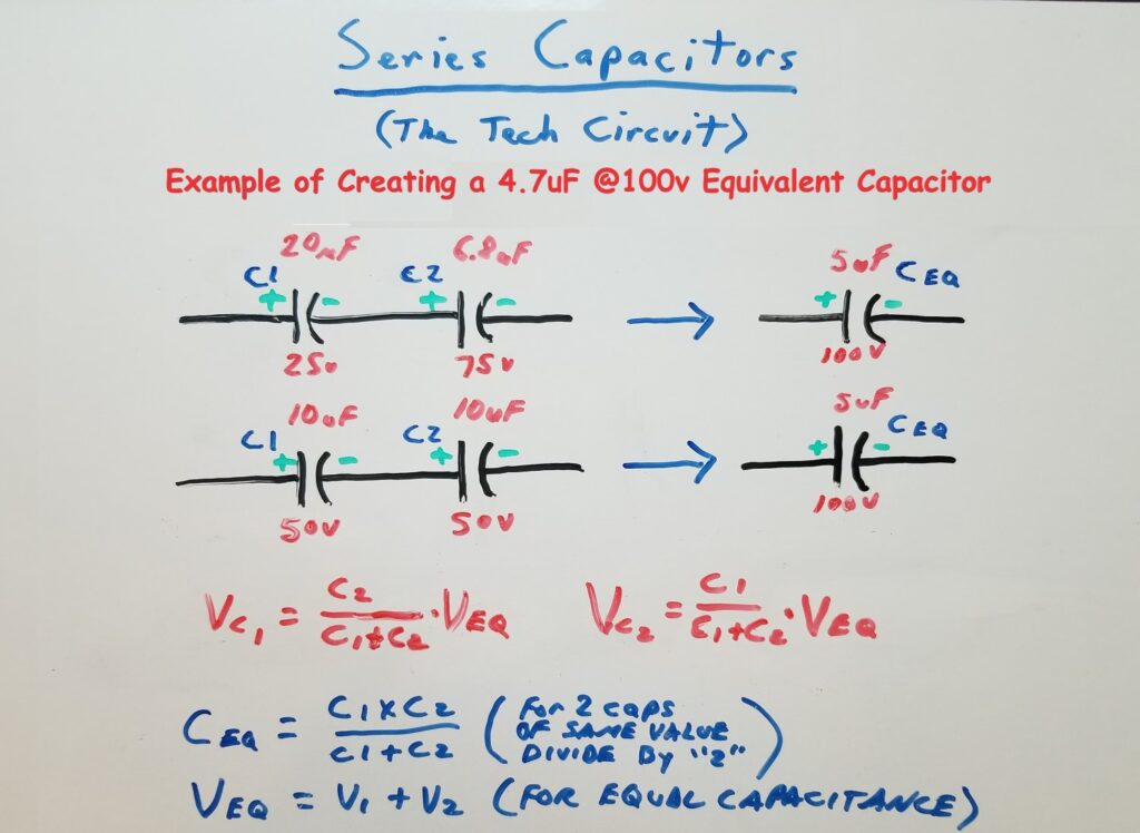
Series Capacitors
When two capacitors are connected in series, the final capacitance (Ceq) is always lower than the value of the lowest capacitor, as determined by the formula shown in the image below. The voltages of the two capacitors are added together to determine the total voltage of the series combination. It’s important to remember that even if you use two series capacitors of the same value, the total voltage may not always divide evenly between them due to differing ESRs (equivalent series resistances). When the capacitors have differing values, the voltage distribution will be uneven. This uneven distribution is caused by their differing reactances (impedances) to AC current. The image below provides two options for creating a 4.7uF capacitor with a 100V equivalent.
Summary
Electrolytic capacitors are a commonly failing component – particularly in power supply applications. The electrolyte is a conductive liquid that is essential for the capacitor’s proper functionality and adherence to circuit specification. Their failure sometimes manifests as physical deformation and leaking – but not always. An ESR meter is essential in identifying a capacitor’s functional issues related to compromised electrolyte.
Replacing capacitors becomes easier when a few simple rules are followed. It is important to consider capacitance, voltage, size, operating hours, temperature, and exercise caution when making alterations to the circuit board.
In parallel arrangements of two capacitors, capacitance is added, and the final voltage value is determined by the lowest voltage rating of the two.
In series arrangements of two capacitors, voltages are added, and the final capacitance can be determined using the formula (C1xC2)/(C1+C2).
The voltage across each capacitor in a series arrangement depends on its capacitance. The smallest capacitor will receive the highest voltage. To find the appropriate values for each capacitor in a series arrangement (for two capacitors), the following formula can be used: Vc1=Vfinal x (C2/(C1+C2)) and Vc2 = Vfinal x (C1/(C1+C2)). Here, Vc1 represents the actual voltage rating of the first replacement capacitor in series, Vc2 represents the actual voltage rating of the second replacement capacitor in series, and Vfinal is the desired voltage rating of the capacitor. It is important to note that due to differences in capacitor ESR (equivalent series resistance), it is not possible to predict the exact voltage distribution across each capacitor. Therefore, it is recommended that each capacitor has a voltage rating equal to that of the original capacitor.
Disclaimer
This blog is intended for experienced or supervised technicians. Always take appropriate safety precautions when dealing with live circuits. For informational purposes only. Utilize the concepts in this blog at your own risk. The Tech Circuit or Steve Morrison assumes no responsibility or liability for any errors or emissions in the content of this blog. The information contained in this blog is provided on an as is basis with no guarantees of completeness, accuracy, usefulness, or timeliness. Never attempt to repair circuit boards unless you are directly supervised by a licensed professional engineer and doing so under approved ISO and UL processes.
Don’t forget:
“Diverting 10 min/day of social media time towards learning something new, is 5 hours of newfound monthly knowledge.” – SM
To DONATE to the Tech Circuit – CLICK HERE
Alphabetical Links to all Tech Circuit Articles and Blogs – CLICK HERE
Links to all Tech Circuit Cheat Sheets/Field References for Appliance/HVAC Techs – CLICK HERE
For additional electrical and electronics learning material for field techs, visit our homepage at http://www.TechCircuit.org or our Facebook group at https://www.facebook.com/groups/746823709133603.
We are a participant in the Amazon Services LLC Associates Program, an affiliate advertising program designed to provide a means for us to earn fees by linking to Amazon.com and affiliated sites.