
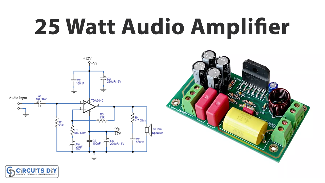
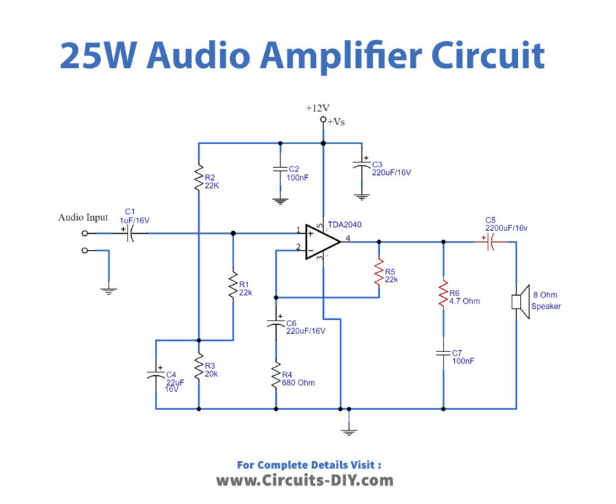
In this tutorial, we are going to make a “25 Watt Audio Power Amplifier Circuit”.
In Analog electronics power amplifiers play the role of backbone. It is designed to maximize the magnitude of the power for the given input signal. In audio-based projects, the operational amplifier increases the voltage of the signal but is unable to provide the current, which is required to drive a load. Here we design a 25W amplifier using a TDA2040 power amplifier IC with an 8 Ohms impedance speaker connected to it. It is a monolithic integrated circuit (25-watt hi-fi audio power amplifier) that comes in a petawatt V package so it occupies less space in PCB, and it can be used as a class AB amplifier.
TDA2040 provides 25 W output power into an 8Ω loudspeaker and it has low harmonic and cross-over distortion to the amplified signal and gives high output current. It can be used in a single or split power supply and takes a wide range of supply voltage up to 40V. It has built-in features internal short circuit protection and thermal shutdown. And it does not require dual supply, electronic components associated with the circuit are abundantly available and are economical too.
Hardware Components
The following components are required to make Audio Power Amplifier Circuit
| S.no | Component | Value | Qty |
|---|---|---|---|
| 1. | IC | TDA2040 | 1 |
| 2. | Resistor | 22KΩ, 680Ω, 4.7Ω, 20KΩ | 3,1,1,1 |
| 3. | Electrolyte Capacitor | 1uF/16V , 220uF/16V , 22uF/16V , 2200uF/16V | 1,2,1,1 |
| 4. | Speaker | – | 1 |
| 5. | Ceramic capacitor | 100nF | 1 |
TDA2040 Pinout
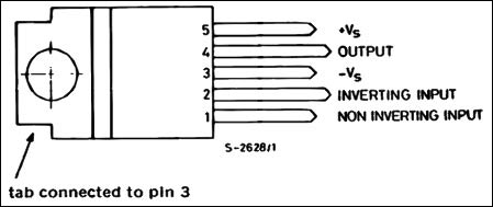
For a detailed description of pinout, dimension features, and specifications download the datasheet of TDA2040
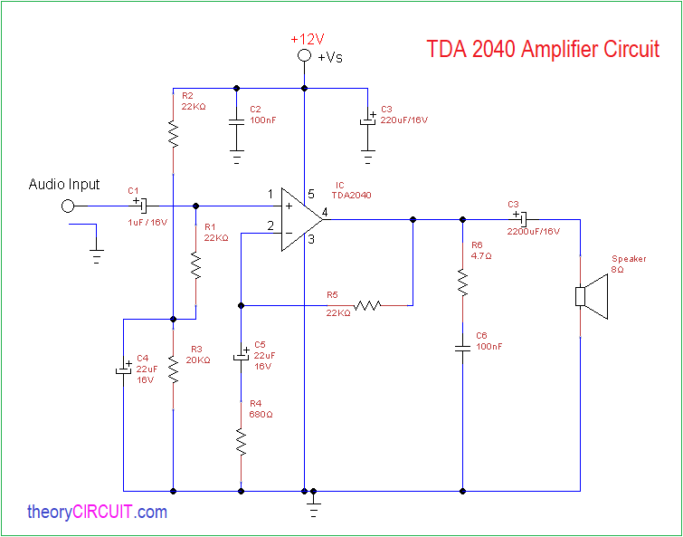
Audio Power Amplifier Circuit
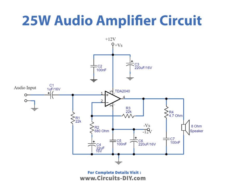
TDA2040 Amplifier – Single Power Supply Circuit Diagram
Working Explanation
In this circuit, the power amplifier is the last stage which is directly connected to the load. Generally, before the power amplifier, the signal is corrected using pre-amplifiers and voltage control amplifiers. Also, in some cases, where tone control is needed, the tone control circuitry is added before the power amplifier. Here first if we want to obtain a perfect peak-to-peak audio output signal for the single power supply circuit, we have to make a dual power supply (Split power). When we employ it, the amplifier takes a mono audio signal and gives mono audio output.
Now the TDA2040 is amplifying the signal and providing 25Watt RMS wattage to the 8 ohms loudspeaker. C2 and C5 are used as decoupling filter capacitors. C1 and R1 are acting as a filter. R2, R3, and C4 are providing the necessary feedback to the power amplifier. R4 and C7 are the snubber circuit to clamp the feedback from the inductive load (Loud Speaker). You can bridge two TDA2040 amplifiers If you need a stereo amplifier. In this configuration, we may lose a few audio negative signal details. But the overall amplification and power delivery performance for both circuits are the same. Here both circuit operation methods are the same but the construction slightly changes due to the power supply connections.
Applications
Can be used in audio-based electronic devices.


