Introduction
The Power Amplifier Circuit is a circuit that amplifies the amount of its input power to drive various loads. It is an electronic circuit that is supposed to enhance the magnitude of the input signal. The audio amplifier circuits’ goal is to provide a noise-free, efficient, and low-distorted audio signal with a larger output magnitude. Audio amplifiers are used in a variety of technologies. The amplifiers normally have two stages: a pre-amplifier that only boosts voltage gain and not current gain, and a power amplifier that requires the audio signal to be power modified. In this tutorial, we are talking about power amplifiers.
Hardware Required
| S.no | Component | Value | Qty |
|---|---|---|---|
| 1. | IC | TA7222AP | 1 |
| 2. | Speaker | – | 1 |
| 3. | Battery | 12v | 1 |
| 4. | Potentiometer | 100K | 1 |
| 5. | Electrolytic Capacitor | 4.7uF, 47uF, 470uF | 1, 2, 2 |
| 6. | Capacitor | 100nF | 1 |
| 7. | Resistor | 200Ω, 27KΩ | 1, 1 |
| 8. | 2-Pin Connector | – | 1 |
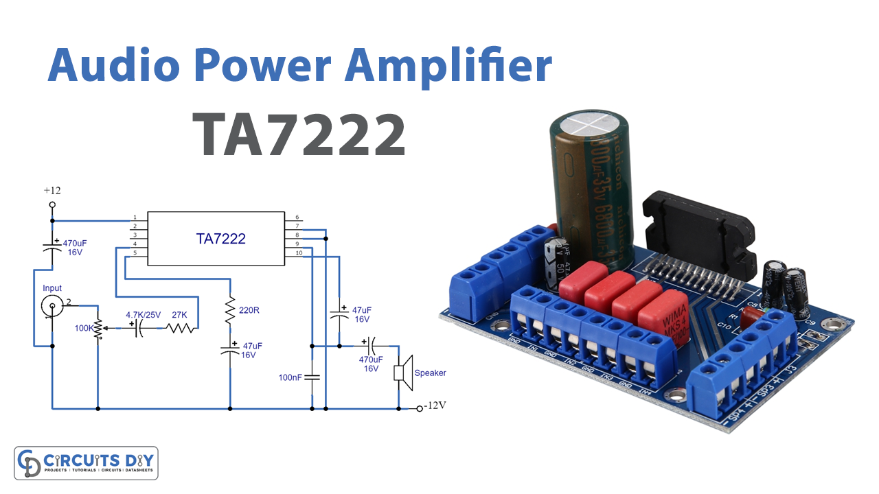
Circuit Diagram
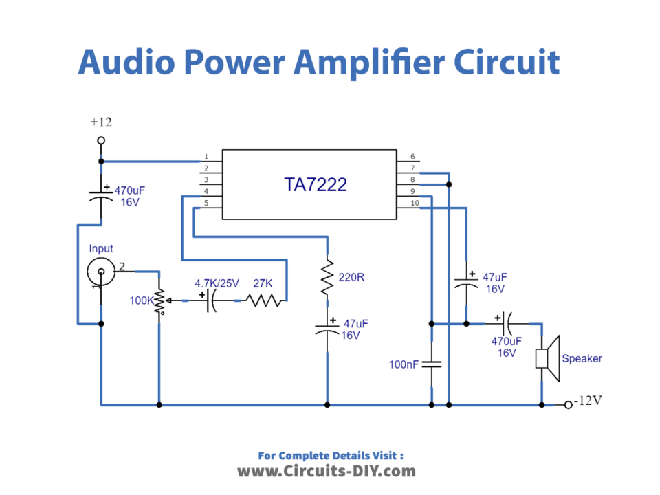
Working Explanation
In this Audio Power Amplifier Circuit, we are using TA7222AP IC. This circuit is capable of producing 5.8 watts of output power. The IC pin 1 receives a 12V input voltage, while pins 2, 3, and 6 remain unconnected. The audio input signal is transmitted to pin 4 using a potentiometer, allowing us to adjust the input volume. The loudspeaker is wired to output pin 9 by a 470F capacitor, and the bootstrap signal is delivered via a 47F capacitor. The R1 resistor is used as a volume controller in this amplifier circuit, which is suited for 2ohms to 8ohms loudspeaker loads at the output. Depending on the load at the output, you can select the c5 capacitor as the bootstrap signal capacitor. The circuit is capable of producing 5.8 watts of output power.
Application and Uses
- Public addressing systems.
- Audio instruments.
- Sound reinforcement system, etc.