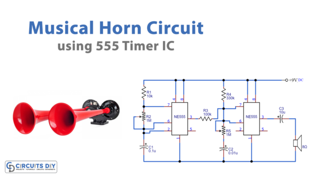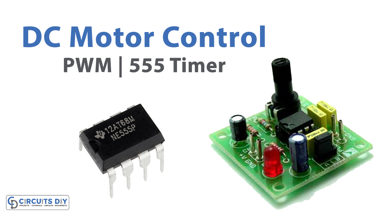
Pulse Width Modulation (PWM) is a technique used for current management, allowing one to manage/control the speed of motors and appliances, heat output of heaters, and provide the advantage of energy efficiency in a relatively quieter manner. The DC motor speed controller circuit as shown in our figure works with 12V while controlling the DC motor using 555 integrated circuits (IC)
Hardware Required
| S.no | Component | Value | Qty |
|---|---|---|---|
| 1. | IC | NE555 Timer | 1 |
| 2. | Transistor | 2N2222, 2N3055 | 1 |
| 3. | Diodes | 1N914, 1N4007 | 2, 2 |
| 4. | Resistor | 1K, 1.5K, 2.2K | 1, 1, 2 |
| 5. | Capacitor | 0.1uF, 1uF | 2, 1 |
| 6. | Potentiometer (P1) | 100K | 1 |
Working Explanation
Through Pulse Width Modulation (PWM), we control the speed by pulsating the motor drive with an “ON-OFF” series. While varying the duty cycle, the fraction of time in which output voltage is “ON” alternatively, when it is “OFF”, the pulse frequency is maintained constantly.
The duty cycle refers to the amount of time the power supply is active. If the duty cycle of the PWM power supply is set to 60%, then the pulse will remain active for 60% of the total time, whereas it, is inactive for 40% of the total time.
The applied motor’s power can be controlled by varying widths of the pulses, resulting in variation of the average DC voltage applied to the motor’s terminals. To control the speed of the motor, you can change or modulate the timing of applied pulses i.e. longer the pulse is “ON”, the faster the motor will rotate and vice versa.
In a nutshell, the wider the pulse width, the more the average voltage applied to motor terminals, and the stronger the magnetic flux inside armature winding, thus, the faster the motor will rotate.
Circuit Diagram

Application and Uses
- Variable speed fan controllers
- VRF HVAC compressor drives
- Hybrid & electric vehicle (EV) motor drive circuits
- LED Dimmers