In this tutorial, we are making a project on a VU meter circuit. A volume unit or VU meter is a device that shows the audio level in audio devices from which a user can maintain a certain audio level and get rid of overloading the output. This circuit is very useful and inexpensive as it is using only a few components such as a transistor, diodes, resistors, capacitors, potentiometer, ampere meter, etc.
Hardware Components
The following components are required to make VU Meter Circuit
| S.no | Component | Value | Quantity |
|---|---|---|---|
| 1. | DC Supply | 9-12V | 1 |
| 2. | Audio input | – | 1 |
| 3. | Transistor | 2N3904 | 1 |
| 4. | Diode | 1N4148 | 2 |
| 5. | Resistor | 1.2K, 220K | 1 |
| 6. | Electrolytic Capacitor | 1µF, 10µF, 47µF | 2, 1, 1 |
| 7. | Potentiometer | 1M | 1 |
| 8. | Ammeter | 1 mA | 1 |
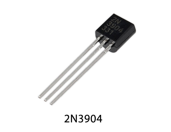
2N3904 Pinout
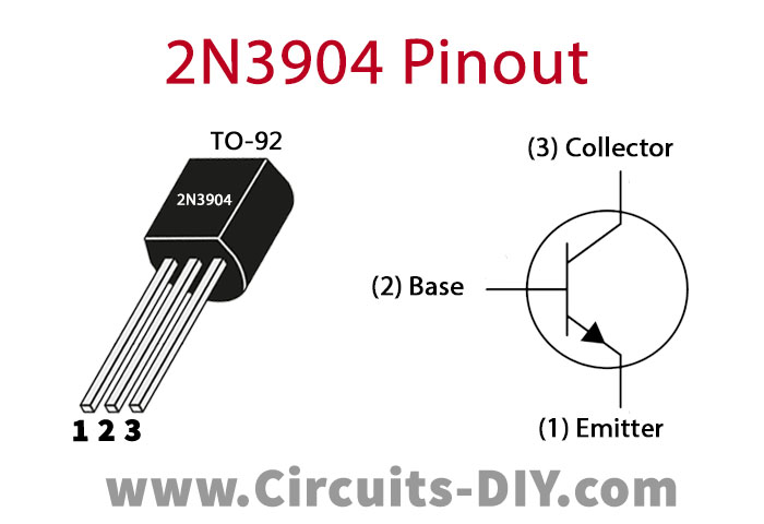
For a detailed description of pinout, dimension features, and specifications download the datasheet of 2N3904
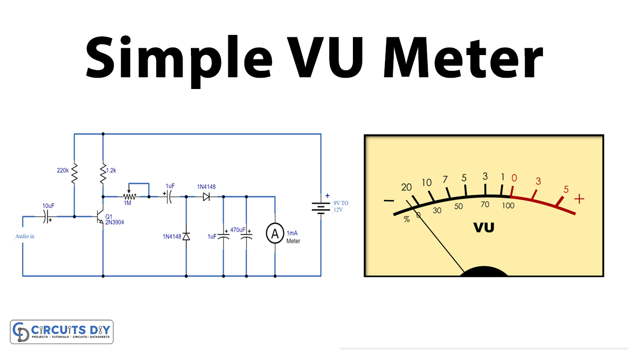
VU Meter Circuit
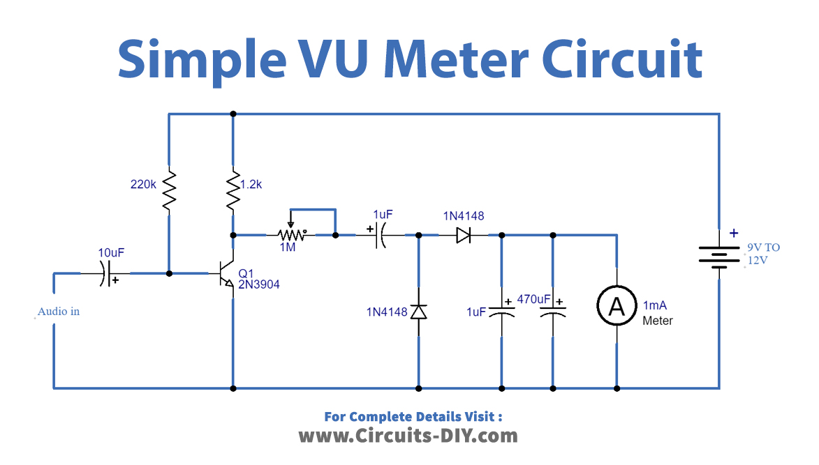
Working Explanation
This circuit can be operated at 9 to 12 volts DC but you can also try low voltage such as 3,5 or 6. The working of this circuit is simple. The audio signal received from the input is passed from a transistor for amplification and then the amplified signal is passed through diodes for rectification. Now, this signal is being fed into the 1A DC meter, in this meter, you can observe the output results. To adjust the sensitivity of this circuit we have used a potentiometer of 1M ohms.
Calibration of the circuit:
After building this circuit you need to do some calibration by adjusting the 1M potentiometer. Connect an audio device with the audio input, slightly start adjusting the potentiometer till you observe readings on the meter, fix the potentiometer at that point. Now your circuit will be ready to use.
Applications and Uses
This circuit can be used with different audio mediums such as
- Vinyl
- CDs
- Streaming (includes youtube and other live broadcasts)