C3BX intake and crank case vent pictures needed
 04-13-2016, 08:01 AM
#1
Instructor

Thread Starter

Does anyone have the edelbrock C3BX intake on their 1966 300 hp engine. If so can you take some pictures of the crank case vent tube and coil arrangement. I need to add the crank case vent to mine and would like to see how you arranged it.
 04-13-2016, 08:32 AM
#2
Team Owner


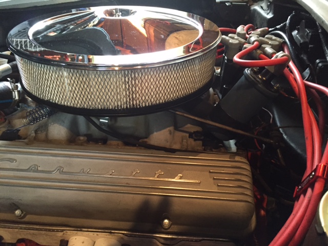
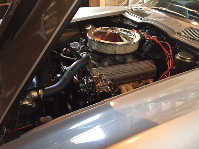
I ran one on my 63 250hp car WITH an AFB carb - nearly identical to what you have.
The crankcase rubber hose went to the metal adapter and down into the engine block through the hole in the large grommet, just like stock. The second pic shows the rubber PCV line coming off the metal crankcase pipe and how it is routed between the coil bracket and distributor and over the vacuum advance line - just like a stock setup.
Third pic is getting my A/C charged...shows the PCV valve on back of AFB.
The C3BX is a great intake.
Hope this helps!
Last edited by Frankie the Fink; 04-13-2016 at 09:03 AM.
04-13-2016, 08:55 AM
#3
Instructor
Thread Starter
I ran one on my 63 250hp car WITH an AFB carb - nearly identical to what you have.
The crankcase rubber hose went to the metal adapter and down into the engine block through the hole just like stock. The second pic shows the rubber PCV line coming off the metal crankcase pipe and how it is routed between the coil bracket and distributor and over the vacuum advance line - just like a stock setup.
Third pic is getting my A/C charged...shows the PCV valve on back of AFB.
The C3BX is a great intake.
Hope this helps!
04-13-2016, 05:18 PM
#4
Team Owner
Member Since: Nov 2005
Location: Beach & High Desert Southern California
Posts: 25,563
Received 2,369 Likes
on
895 Posts

The routing shown is the 63 setup for the pcv. It draws air from inside the air filter into the oil fill tube, and then through the lifter valley to the tomato can oil separator at the back of the valley, and then up to the pcv valve plumbed to the port under the carburetor.
It works.
On my 350 block, I do not have the tomato can in the valley like a 327. I drilled a port in the back of the block for a vent. This port has a baffle in the valley, and is piped up to an oil separator located in the coil bracket, hidden under the ignition shielding tin. From there it is piped to the carburetor.
The service manuals show how the PCV piping changed through the model years, so there are lots of options.
04-13-2016, 07:55 PM
#6
Team Owner
Not sure....the upper radiator hose was a generic version from the local NAPA trimmed to fit. The T-stat housing was included with the manifold when I sold it and I couldn't say what it was, specifically. All that stuff has been gone for a couple of years now as the car has been taken back to stock form... It was a great running setup - just not original...
04-13-2016, 09:24 PM
#7
Team Owner


Member Since: Oct 2000
Location: Washington Michigan
Posts: 38,899
Received 1,859 Likes
on
1,102 Posts
 04-15-2016, 07:40 AM
#9
Melting Slicks


Member Since: Apr 2009
Location: Virginia Beach VA
Posts: 2,476
Received 574 Likes
on
321 Posts
C2 of the Year Finalist - Modified 2020
C2 of Year Finalist (performance mods) 2019
Frankie, did you notice a difference in the performance when you changed back to oem?
04-15-2016, 07:44 AM
#10
Team Owner
HOWEVER, as part of the intake swap back to original I had the distributor overhauled by Lars (one of the last he did before quitting) and he recurved it and fixed some problems. It went back on the car during the intake R&R.
So whatever I lost with the intake/carb swap I more than recovered with the distributor improvements.
So, to answer your question in one word, no....

Last edited by Frankie the Fink; 04-15-2016 at 07:45 AM.
The following users liked this post:
MarkC (04-15-2016)
05-01-2016, 04:03 PM
#11
Instructor
Thread Starter
I ran one on my 63 250hp car WITH an AFB carb - nearly identical to what you have.
The crankcase rubber hose went to the metal adapter and down into the engine block through the hole in the large grommet, just like stock. The second pic shows the rubber PCV line coming off the metal crankcase pipe and how it is routed between the coil bracket and distributor and over the vacuum advance line - just like a stock setup.
Third pic is getting my A/C charged...shows the PCV valve on back of AFB.
The C3BX is a great intake.
Hope this helps!
 05-01-2016, 04:29 PM
#12
Team Owner
Noooo problem!