Maybe it is easier to find BA6138, it is another good compressor IC for driving VU meters.
1/4 (TA7318P) or 1/2 (BA6138) root square is just linear difference, easy to adjust with trimmers.
Important is root square compression so that dynamic of music is compressed that VU meter can cover that wide response.
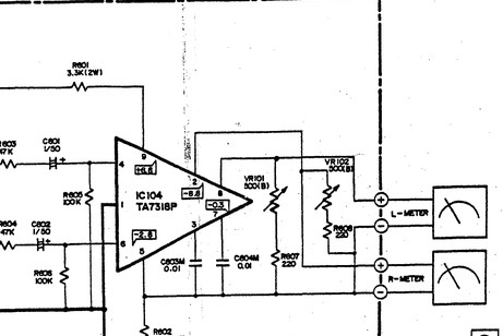
Another amplifier, Technics SE A900 use BA6138 to drive similar VU meters.
1/4 (TA7318P) or 1/2 (BA6138) root square is just linear difference, easy to adjust with trimmers.
Important is root square compression so that dynamic of music is compressed that VU meter can cover that wide response.
Another amplifier, Technics SE A900 use BA6138 to drive similar VU meters.
Last edited:
Thank you all very much for your help, I do have all the components from the Uher meaning I do have the original TA7318P in hand, do you suggest using it and copying the original driver circuit on a perforated board? I didn't like the way these meters were originally driven by the TA7318P because they did hardly move as they are power output meters, that is why I am looking for a different driver circuit making these meters more bouncy")
if you are not interested in the accuracy of the reading, just the dancing meter, just use a diode, a capacitor and 3 pots and have a switch to select 3, 30, 300 watts.
I used to have a log led display with a switch label 1 watt, 100 watts. People were disappointed when they would flip the switch and the amp didn't get any louder.
It was like having a volume control that went to 12 where the other brand only went to 10.
I bought several Kenwood amplifiers on ebay KM106, KM206. $50 each. The led power display only has 5 leds but 14 openings in the front panel to display .1 to 150 watts. As the leds get brighter more openings get illuminated. The accuracy of the display is a pure guess.

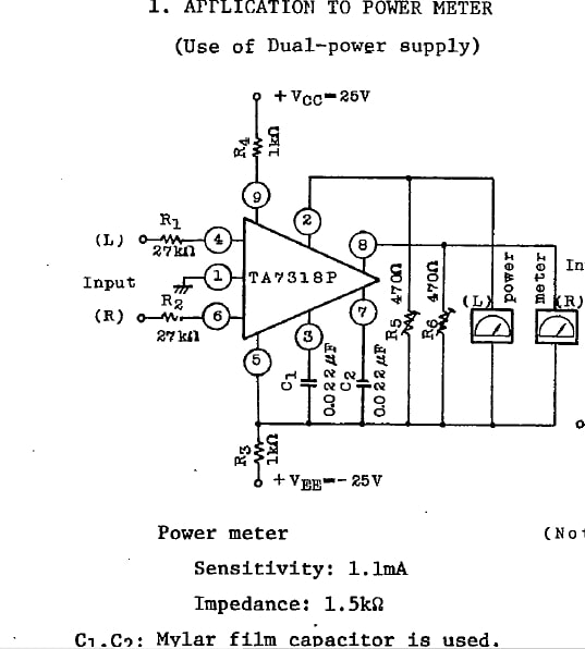
After studding Uher's schematic and the TA7318P datasheet I am thinking of following the schematic given in the datasheet and build a driver for the meters by calculating and adapting accordingly the components values to my needs, this way I'll use the TA7318P I already have.
Last edited:
Yes it is, I think I'm going to use a 2X12V AC transformer that I already have, a simple circuit with a bridge rectifier or diodes and a couple of caps to take 17-0-17V DC after rectification for powering the driver.
I'll change the film capacitors values as you propose and I hope it will work good enough.
I'll change the film capacitors values as you propose and I hope it will work good enough.
Last edited:
...I didn't like the way these meters were originally driven by the TA7318P because they did hardly move....
Then use the original driver (intact if possible) but turn the sensitivity way up so it pins on your loudest music.
You "need" some processor. You listen over a 10,000:1 range of loudness. You can't reasonably read 100:1 on a mechanical meter, and can hardly see more than 10:1 without squinting. The fourth-root conversion changes 10,000:1 into 10:1 so you see most of what you hear.
If I remember my maths correctly ??
1/4 root is the same as anti-log((log x) / 4)
You could use a log amplifier followed by an attenuator then an anti-log amplifier.
Using this approach you could play with the attenuator to get 1/5 or even 1/6 root for even more compression.
If you Google a log amp it is a simple circuit as is the anti-log.
The anti-log just swaps the diode and the resistor.
Diagram 3 is food for thought.
Attachments


Last edited:
Thank you KatieandDad for your suggestions, I've started to build the driver on a protoboard, I don't think sensitivity is my broblem, when I said "they did hardly move" I ment they were not bouncy but kept a certain level depending on how loud the music was playing, instead I think as nironiro mentioned it has to do with recovery time, so I'll try with 2.2nF caps to reduce peak hold time and see how it works.
Last edited:
Indication scheme in the lower right corner.
Стр. 36 журнала <<Радио>> № 1 за 1977 год
Стр. 36 журнала <<Радио>> № 1 за 1977 год
hello, after I read datasheet, and look installation recommendation on a*iexpress that unit was designed to connect in output of amplifier (speaker out) in example from datasheet, when connected to 100 watt RMS output amplifier R1 value is 27k ohm. I've already make this vu, but I need to connect itn after line out / headphone out from soundcard or recorder (zoom h1). so how to calculate R1 to match input source?
Attachments

- Home
- Amplifiers
- Solid State
- Analog VU meter in power amplifier